Manufacturers of Weld Neck Flanges
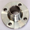 we offers a range of Weld Neck Flanges. As the name implies, it is called as a neck part of the flange which is being welded to the last points of the piping system. Weld Neck Flanges has a wide-ranging tapering focal point and are commonly used for high pressure applications. In fact, it is being designed to shift the pressure within the pipe, in a way to dip the high pressure concentration towards the bottom of the flange. Weld Neck Flanges are also quite known from other forms by their wide-ranging pointed centre and modest development of thickness in the butt weld area, by joining them with the pipe
½” (15 NB) to 60” (1500NB) in 150 LBS, 300 LBS, 600 LBS, 900 LBS, 1500 LBS, 2500 LBS ASA 150, ASA 300, PN 6,10,16,25, 40,64,100,160 ETC. available with NACE MR 01-75
½” (15NB) to 60” (1500NB)
Class / Pressure : 150#, 300#, 600#, 900#, 1500#, 2500# PN6, PN10, PN16, PN25, PN40, PN64
B16.5, BS4504, EN-1092, B16.36, B16.47, B16.48, MSS SP44
STD : ANSI Flanges, ASME Flanges, DIN Flanges, EN Flanges, BS Flanges, API, JIS, NACE etc.
Dimensional accuracy, Corrosion resistance, High efficiency, Excellent finish, Durable
Stainless Steel Weld Neck Flanges :
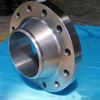 Standard : ASTM / ASME A/SA 182
 Grade : F 304, 304L, 304H, 309S, 309H, 310S, 310H, 316, 316TI, 316H, 316L, 316LN, 317, 317L, 321, 321H, 347, 347H, 904L
Duplex Steel Weld Neck Flanges :
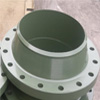 Standard : ASTM / ASME A/SA 182
 Grade : F 44, F 45, F51, F 53, F 55, F 60, F 61
Aluminium Weld Neck Flanges :
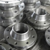 Standard : ASTM B247, B361.
 Grade : 2024, 6061, 6063, 6101, 7075.
Titanium Weld Neck Flanges :
Grade : Grade 1, Grade 2, Grade 4, Grade 5, Grade 6, Grade 7, Grade 9, Grade 19, Grade 23
Carbon Steel Weld Neck Flanges :
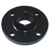 Standard : ASTM A 105/A694/ A350 LF3/A350 LF2.
 Grade : F42/46/52/56/60/65/70
Low Temperature Carbon Steel Weld Neck Flanges :
Alloy Steel Weld Neck Flanges :
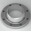 Standard : ASTM A182
 Grade : F1/F5/F9/F11/F22/F91
Copper Alloy Weld Neck Flanges :
Grade : UNS NO. C 70600 (CU -NI- 90/10), C 71500 (CU -NI- 70/30) C 71640
Nickel Alloy Weld Neck Flanges :
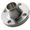 Standard : ASTM / ASME SB 564 / 160 / 472
• Nickel 200 – UNS N02200 • Nickel 201 – UNS N02201 • Monel 400 – UNS N04400
• Monel K500 – UNS N05500 • Inconel K600 – UNS N06600 • Inconel 601 – UNS N06601
• Inconel 625 – UNS N06625 • Inconel 800 – UNS N08800 • Inconel 800H – UNS N08810
• Inconel 825 – UNS N08825 • Hastelloy C276 – UNS N10276 • Alloy 20 – UNS N08020
Advantages of Weld Neck Flanges
Suitable for high pressure and high heat applications:
Some of the flange materials such as stainless steel are highly resistant to heat. The extreme pressure that is developed in piping applications throughout the industry calls for high-pressure resistance. A welded flange is stronger that a bolt-on flange. The bolt-on flange sometimes calls for a gasket that could cause leaks.
Reduced friction and interference:
The welded connection will not interfere with the flow of the fluid. With the reduced friction, the fluid will not develop turbulence allowing for less vibration and a smoother flow. Less turbulence will also allow for a quieter operation.
Easier Alignment:
The neck of the flange will allow for a more accurate easier alignment to the pipe saving time. The alignment is also much more precise with less tolerance.
Testing of the pipe and joints are easier:
Radiography test can be much easier to perform because of the easy access the flanges allow.
Durable connection:
Stress on the inside is transferred to the neck of the flange taking the pressure off the pipe allowing for a more permanent connection.
Leakage prevention:
In most applications using the weld neck flanges, the weld is made inside and outside of the flange. This will provide a connection that is more leak proof.
Ease of installation:
When using the butt flanges it is easier to determine pipe length applications because the calculations do not have to account for the space taken up by threads on bolt-on applications. Slip-on flanges also require calculation using the insertion amount.
ANSI B16.5 Weld Neck Flanges, ASME B.16.5 Weld Neck Pipe Flanges, DIN Weld Neck Flange
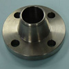 We are specialized in manufacturing high standard quality of Slip-on flanges. Weld Neck Flanges are widely used in special circumstances with their main advantage being that they can be attached to the pipe without welding. We are one of the leading manufacturer and supplier of steel WNRF Weld Neck flanges in India, we can supply stainless steel, carbon steel and nickel alloy WNRF Weld Neck flanges.
WNRF Weld Neck flanges, steel WNRF Weld Neck flanges are available with following specifications:
We proffer slip-on pipe flanges that are being manufactured at our best services to companies in a range of industries including power generation, shipbuilding, petrochemical plants, waste water treatment plants, oil refineries, paper mills, turnkey projects and pharmaceutical plants among others.
Specification
Standards: ANSI B16.47 Series A & B, ANSI B16.5, API-605, MSS SP44, ASA, EN1092, BS 4504, DIN
Type: Weld Neck Flanges / WNRF
Size: ½” (15 NB) to 48″ (1200NB)
Class : 150 Class, 300 Class, 400 Class, 600 Class, 900 Class, 1500 Class, 2500 Class, PN6, PN10, PN16, PN25, PN40, PN64 etc.
Material: Stainless Steel, Duplex, Super Duplex, Nickel Alloys, Alloy Steel, Carbon Steel, Low temperature Steel
Material Grade:
Stainless Steel Weld Neck Flanges: ASTM A 182, A 240 F 304, 304L, 304H, 316, 316L, 316Ti, 310, 310S, 321, 321H, 317, 347, 347H, 904L
Duplex & Super Duplex Steel Weld Neck Flanges: ASTM A182 / ASME SA182, F 44, F 45, F51, F 53, F 55, F 60, F 61
Carbon Steel Weld Neck Flanges: ASTM A105 / ASME SA105, ASTM A350 / ASME SA350, ASTM A181 LF 2 / A516 Gr.70 A36, A694 F42, F46, F52, F60, F65, F70
Low Temperature Carbon Steel Weld Neck Flange (LTCS WNRF): Flange, A350 LF2/A350 LF3
Alloy Steel Weld Neck Flanges: ASTM A182 / ASME SA182 & A387 F1, F5, F9, F11, F12, F22, F91
Nickel Alloy Weld Neck Flanges: ASTM / ASME SB 564 / 160 / 472, UNS 2200 ( Nickel 200 ), UNS 2201 (Nickel 201 ), UNS 4400 (Monel 400 ), UNS 8020 ( Alloy 20 / 20 CB 3, UNS 8825 Inconel (825), UNS 6600 (Inconel 600 ), UNS 6601 ( Inconel 601 ), UNS 6625 (Inconel 625), UNS 10276 ( Hastelloy C 276 )
class d Weld Neck Flange dimensions
Dimensions in Inches
| Nom. size |
Outside Ø (OD) |
Slip-on Bore (ID) |
No. of Bolt Holes |
Ø of Holes |
Ø Bolt Circle (BC) |
Thickness (T) |
Weight (lbs) |
||
| Slip-on | Blind | Slip-on | Blind | ||||||
| 2 | 6.00 | 2.44 | 4 | 0.750 | 4.75 | 0.625 | 0.625 | 3.90 | 4.7 |
| 2.5 | 7.00 | 2.94 | 4 | 0.750 | 5.50 | 0.625 | 0.625 | 5.30 | 6.5 |
| 3 | 7.50 | 3.57 | 4 | 0.750 | 6.00 | 0.625 | 0.625 | 5.70 | 7.5 |
| 4 | 9.00 | 4.57 | 8 | 0.750 | 7.50 | 0.625 | 0.625 | 7.70 | 10.6 |
| 5 | 10.00 | 5.66 | 8 | 0.875 | 8.50 | 0.625 | 0.650 | 8.80 | 13.6 |
| 6 | 11.00 | 6.72 | 8 | 0.875 | 9.50 | 0.688 | 0.693 | 10.70 | 17.7 |
| 8 | 13.50 | 8.72 | 8 | 0.875 | 11.75 | 0.688 | 0.812 | 15.30 | 31.8 |
| 10 | 16.00 | 10.88 | 12 | 1.000 | 14.25 | 0.688 | 0.953 | 19.20 | 51.7 |
| 12 | 19.00 | 12.88 | 12 | 1.000 | 17.00 | 0.812 | 1.117 | 33.10 | 86.7 |
| 14 | 21.00 | 14.19 | 12 | 1.125 | 18.75 | 0.938 | 1.133 | 46.90 | 107.4 |
| 16 | 23.50 | 16.19 | 16 | 1.125 | 21.25 | 1.000 | 1.265 | 60.10 | 149.8 |
| 18 | 25.00 | 18.19 | 16 | 1.250 | 22.75 | 1.062 | 1.331 | 63.60 | 177.7 |
| 20 | 27.50 | 20.19 | 20 | 1.250 | 25.00 | 1.125 | 1.448 | 79.40 | 233.6 |
| 22 | 29.50 | 22.19 | 20 | 1.375 | 27.25 | 1.188 | 1.568 | 89.90 | 290.5 |
| 24 | 32.00 | 24.19 | 20 | 1.375 | 29.50 | 1.250 | 1.661 | 113.40 | 364.5 |
| 26 | 34.25 | 26.25 | 24 | 1.375 | 31.75 | 1.312 | 1.786 | 128.00 | 448.2 |
| 28 | 36.50 | 28.25 | 28 | 1.375 | 34.00 | 1.312 | 1.906 | 140.50 | 542.6 |
| 30 | 38.75 | 30.25 | 28 | 1.375 | 36.00 | 1.375 | 2.008 | 163.30 | 647.3 |
| 32 | 41.75 | 32.25 | 28 | 1.625 | 38.50 | 1.500 | 2.150 | 210.10 | 798.6 |
| 34 | 43.75 | 34.25 | 32 | 1.625 | 40.50 | 1.500 | 2.252 | 219.10 | 916.9 |
| 36 | 46.00 | 36.25 | 32 | 1.625 | 42.75 | 1.625 | 2.370 | 259.40 | 1071.4 |
| 38 | 48.75 | 38.25 | 32 | 1.625 | 45.25 | 1.625 | 2.506 | 299.80 | 1278.2 |
| 40 | 50.75 | 40.25 | 36 | 1.625 | 47.25 | 1.625 | 2.609 | 311.10 | 1440.1 |
| 42 | 53.00 | 42.25 | 36 | 1.625 | 49.50 | 1.750 | 2.729 | 361.70 | 1648.1 |
| 44 | 55.25 | 44.25 | 40 | 1.625 | 51.75 | 1.750 | 2.849 | 385.00 | 1868.3 |
| 48 | 59.50 | 48.25 | 44 | 1.625 | 56.00 | 1.875 | 3.072 | 457.30 | 2340.7 |
| 54 | 66.25 | 54.25 | 44 | 1.875 | 62.75 | 2.125 | 3.435 | 610.60 | 3236.7 |
| 60 | 73.00 | 60.25 | 52 | 1.875 | 69.25 | 2.250 | 3.779 | 759.10 | 4327.6 |
| 66 | 80.00 | 66.25 | 52 | 1.875 | 76.00 | 2.500 | 4.136 | 1017.00 | 5722.2 |
| 72 | 86.50 | 72.25 | 60 | 1.875 | 82.50 | 2.625 | 4.480 | 1198.20 | 7249.0 |
| 78 | 93.00 | 78.25 | 64 | 2.125 | 89.00 | 2.750 | – | 1368.90 | – |
| 84 | 99.75 | 84.25 | 64 | 2.125 | 95.50 | 2.875 | – | 1639.70 | – |
| 90 | 106.50 | 90.25 | 68 | 2.438 | 102.00 | 3.000 | – | 1878.30 | – |
| 96 | 113.25 | 96.25 | 68 | 2.438 | 108.50 | 3.250 | – | 2298.30 | – |
| 102 | 120.00 | 102.25 | 72 | 2.688 | 114.50 | 3.250 | – | 2494.20 | – |
| 108 | 126.75 | 108.25 | 72 | 2.688 | 120.75 | 3.375 | – | 2892.50 | – |
| 120 | 140.25 | 120.25 | 76 | 2.938 | 132.75 | 3.500 | – | 3568.50 | – |
| 132 | 153.75 | 132.25 | 80 | 3.188 | 145.75 | 3.875 | – | 4628.60 | – |
| 144 | 167.25 | 144.25 | 84 | 3.438 | 158.25 | 4.125 | – | 5698.20 | – |
class e Weld Neck Flange dimensions
Dimensions in Inches
| Nom. size |
Outside Ø (OD) |
Slip-on Bore (ID) |
No. of Bolt Holes |
Ø of Holes |
Ø Bolt Circle (BC) |
Thickness (T) |
Weight (lbs) |
||
| Slip-on | Blind | Slip-on | Blind | ||||||
| 4 | 9.00 | 4.57 | 8 | 0.750 | 7.50 | 1.125 | 1.125 | 13.90 | 19.2 |
| 5 | 10.00 | 5.66 | 8 | 0.875 | 8.50 | 1.188 | 1.188 | 16.30 | 24.8 |
| 6 | 11.00 | 6.72 | 8 | 0.875 | 9.50 | 1.313 | 1.313 | 20.40 | 33.6 |
| 8 | 13.50 | 8.72 | 8 | 0.875 | 11.75 | 1.500 | 1.500 | 33.40 | 60.8 |
| 10 | 16.00 | 10.88 | 12 | 1.000 | 14.25 | 1.563 | 1.563 | 43.70 | 84.9 |
| 12 | 19.00 | 12.88 | 12 | 1.000 | 17.00 | 1.750 | 1.750 | 71.30 | 135.9 |
| 14 | 21.00 | 14.19 | 12 | 1.125 | 18.75 | 1.875 | 1.875 | 93.70 | 177.7 |
| 16 | 23.50 | 16.19 | 16 | 1.125 | 21.25 | 2.000 | 2.000 | 120.10 | 236.8 |
| 18 | 25.00 | 18.19 | 16 | 1.250 | 22.75 | 2.125 | 2.125 | 127.30 | 283.7 |
| 20 | 27.50 | 20.19 | 20 | 1.250 | 25.00 | 2.375 | 2.375 | 167.70 | 383.2 |
| 24 | 32.00 | 24.19 | 20 | 1.375 | 29.50 | 2.625 | 2.625 | 234.30 | 576.1 |
| 26 | 34.25 | * | 24 | 1.375 | 31.75 | 2.750 | 2.750 | * | 690.1 |
| 28 | 36.50 | * | 28 | 1.375 | 34.00 | 2.750 | 2.750 | * | 782.9 |
| 30 | 38.75 | * | 28 | 1.375 | 36.00 | 2.875 | 2.875 | * | 926.8 |
| 36 | 46.00 | * | 32 | 1.625 | 42.75 | 3.125 | 3.209 | * | 1450.7 |
| 38 | 48.75 | * | 32 | 1.625 | 45.25 | 3.125 | 3.394 | * | 1731.1 |
| 40 | 50.75 | * | 36 | 1.625 | 47.25 | 3.250 | 3.533 | * | 1950.2 |
| 42 | 53.00 | * | 36 | 1.625 | 49.50 | 3.375 | 3.695 | * | 2231.5 |
| 44 | 55.25 | * | 40 | 1.625 | 51.75 | 3.375 | 3.857 | * | 2529.4 |
| 48 | 59.50 | * | 44 | 1.625 | 56.00 | 3.500 | 4.159 | * | 3169.0 |
| 54 | 66.25 | * | 44 | 1.875 | 62.75 | 3.750 | 4.651 | * | 4382.5 |
| 60 | 73.00 | * | 52 | 1.875 | 69.25 | 3.875 | 5.116 | * | 5858.7 |
| 66 | 80.00 | * | 52 | 1.875 | 76.00 | 4.250 | 5.601 | * | 7749.0 |
| 72 | 86.50 | * | 60 | 1.875 | 82.50 | 4.375 | 6.066 | * | 9815.3 |
| 78 | 93.00 | * | 64 | 2.125 | 89.00 | 4.750 | * | ||
| 84 | 99.75 | * | 64 | 2.125 | 95.50 | 4.750 | * | ||
| 90 | 106.50 | * | 68 | 2.438 | 102.00 | 5.125 | * | ||
| 96 | 113.25 | * | 68 | 2.438 | 108.50 | 5.125 | * | ||
| 102 | 120.00 | * | 72 | 2.688 | 114.50 | 5.500 | * | ||
| 108 | 126.75 | * | 72 | 2.688 | 120.75 | 5.500 | * | ||
| 120 | 140.25 | * | 76 | 2.938 | 132.75 | 5.875 | * | ||
| 132 | 153.75 | * | 80 | 3.188 | 145.75 | 6.250 | * | ||
| 144 | 167.25 | * | 84 | 3.438 | 158.25 | 6.750 | * | ||
* The purchaser shall specify the ID of the flange for nominal pipe sizes 26 in. and larger. The diameter of the flange bore shall not exceed the pipe OD by more than .25 in.
en 1092-1 Weld Neck Flange
Weld Neck flanges EN 1092-1 Type 01
 Facing Type A, all faces machined, full thickness
Available from stock in material 1.4307 and 1.4571
On request with inspection certificate EN 10204/ 3.1 + AD2000-W2/W9
*) replaces DIN 2576
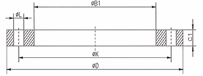
PN 10
| DN | Pipe OD | B1 | D | C1 | K | L | Qtty. | weight |
| Up to DN 40 see PN40 | ||||||||
| From DN 50 to DN 150 see PN16! | ||||||||
| 200 | 219,1 | 221,5 | 340 | 24 | 295 | 22 | 8 | 9,27 |
| 206,0** | 208,0 | 340 | 24 | 295 | 22 | 8 | 9,27 | |
| 250 | 273,0 | 276,5 | 395 | 26 | 350 | 22 | 12 | 11,80 |
| 256,0** | 258,0 | 395 | 26 | 350 | 22 | 12 | 11,80 | |
| 300 | 323,9 | 327,5 | 445 | 26 | 400 | 22 | 12 | 13,60 |
| 306,0*** | 309,0 | 445 | 26 | 400 | 22 | 12 | 13,60 | |
| 350 | 355,6 | 359,5 | 505 | 30 | 460 | 22 | 16 | 20,40 |
| 400 | 406,4 | 411,0 | 565 | 32 | 515 | 26 | 16 | 27,50 |
| 450 | 457,0 | 462,0 | 615 | 36 | 565 | 26 | 20 | 33,60 |
| 500 | 508,0 | 513,5 | 670 | 38 | 620 | 26 | 20 | 40,20 |
| 600 | 610,0 | 616,5 | 780 | 42 | 725 | 30 | 20 | 54,50 |
Weld Neck Flange PN 16
| DN | Pipe OD | B1 | D | C1 | K | L | Qtty. | weight |
| Up to DN 40 see PN40 | ||||||||
| 50 | 60,3 | 61,5 | 165 | 20 | 125 | 18 | 4 | 2,73 |
| 54,0** | 55,0 | 165 | 20 | 125 | 18 | 4 | 2,73 | |
| 65 | 76,1 | 77,5 | 185 | 20 | 145 | 18 | 8 | 3,16 |
| 70,0** | 71,0 | 185 | 20 | 145 | 18 | 8 | 3,16 | |
| 80 | 88,9 | 90,5 | 200 | 20 | 160 | 18 | 8 | 3,60 |
| 84,0** | 85,5 | 200 | 20 | 160 | 18 | 8 | 3,60 | |
| 100 | 114,3 | 116,0 | 220 | 22 | 180 | 18 | 8 | 4,39 |
| 106,0** | 107,5 | 220 | 22 | 180 | 18 | 8 | 4,39 | |
| 125 | 139,7 | 141,5 | 250 | 22 | 210 | 18 | 8 | 5,41 |
| 131,0** | 132,5 | 250 | 22 | 210 | 18 | 8 | 5,41 | |
| 150 | 168,3 | 170,5 | 285 | 24 | 240 | 22 | 8 | 7,14 |
| 156,0** | 157,5 | 285 | 24 | 240 | 22 | 8 | 7,14 | |
| 200 | 219,1 | 221,5 | 340 | 26 | 295 | 22 | 12 | 9,73 |
| 250 | 273,0 | 276,5 | 405 | 29 | 355 | 26 | 12 | 14,20 |
| 300 | 323,9 | 327,5 | 460 | 32 | 410 | 26 | 12 | 19,00 |
| 350 | 355,6 | 359,5 | 520 | 35 | 470 | 26 | 16 | 28,20 |
| 400 | 406,4 | 411,0 | 580 | 38 | 525 | 30 | 16 | 35,90 |
| 450 | 457,0 | 462,0 | 640 | 42 | 585 | 30 | 20 | 46,10 |
| 500 | 508,0 | 513,5 | 715 | 46 | 650 | 33 | 20 | 64,00 |
Weld Neck Flange PN 25
| DN | Pipe OD | B1 | D | C1 | K | L | Qtty. | weight |
| Bis DN 150 sind Flansche mit Nenndruck 16 zu verwenden! | ||||||||
| 200 | 219,1 | 221,5 | 360 | 32 | 310 | 26 | 12 | 14,30 |
| 250 | 273,0 | 276,5 | 425 | 35 | 370 | 30 | 12 | 20,10 |
| 300 | 323,9 | 327,5 | 485 | 38 | 430 | 30 | 16 | 26,60 |
Weld Neck Flange PN 40
| DN | Pipe OD | B1 | D | C1 | K | L | Qtty. | weight |
| 10 | 17,2 | 18,0 | 90 | 14 | 60 | 14 | 4 | 0,61 |
| 15 | 21,3 | 22,0 | 95 | 14 | 65 | 14 | 4 | 0,67 |
| 20 | 26,9 | 27,5 | 105 | 16 | 75 | 14 | 4 | 0,94 |
| 25 | 33,7 | 34,5 | 115 | 16 | 85 | 14 | 4 | 1,11 |
| 32 | 42,4 | 43,5 | 140 | 18 | 100 | 18 | 4 | 1,82 |
| 40 | 48,3 | 49,5 | 150 | 18 | 110 | 18 | 4 | 2,08 |
| 44,5** | 45,5 | 150 | 18 | 110 | 18 | 4 | 2,08 | |
| 50 | 60,3 | 61,5 | 165 | 20 | 125 | 18 | 4 | 2,73 |
| 65 | 76,1 | 77,5 | 185 | 22 | 145 | 18 | 8 | 3,48 |
| 80 | 88,9 | 90,5 | 200 | 24 | 160 | 18 | 8 | 4,32 |
| 100 | 114,3 | 116,0 | 235 | 26 | 190 | 22 | 8 | 6,07 |
| 125 | 139,7 | 141,5 | 270 | 28 | 220 | 26 | 8 | 8,19 |
| 150 | 168,3 | 170,5 | 300 | 30 | 250 | 26 | 8 | 10,30 |
** Dimension not included in EN 1092-1
Additional dimensions, pressure rates and materials, as well as different facings on request
flange slip on 10k
Flange – Slip-On Type
|
JIS B2220 – 10K
|
||||||||
|
Size
|
d
|
D
|
C
|
No.
|
h
|
t
|
Weight (kg)
|
|
|
SO
|
BL
|
|||||||
|
010
|
17.8
|
90
|
65
|
4
|
15
|
12
|
0.52
|
0.54
|
|
015
|
22.2
|
95
|
70
|
4
|
15
|
12
|
0.57
|
0.61
|
|
020
|
27.7
|
100
|
75
|
4
|
15
|
14
|
0.73
|
0.79
|
|
025
|
34.5
|
125
|
90
|
4
|
19
|
14
|
1.13
|
1.24
|
|
032
|
43.2
|
135
|
100
|
4
|
19
|
16
|
1.48
|
1.66
|
|
040
|
49.1
|
140
|
105
|
4
|
19
|
16
|
1.56
|
1.81
|
|
050
|
61.1
|
155
|
120
|
4
|
19
|
16
|
1.88
|
2.23
|
|
065
|
77.1
|
175
|
140
|
4
|
19
|
18
|
2.60
|
3.24
|
|
080
|
90.0
|
185
|
150
|
8
|
19
|
18
|
2.61
|
3.50
|
|
090
|
102.6
|
195
|
160
|
8
|
19
|
18
|
2.76
|
4.00
|
|
100
|
115.4
|
210
|
175
|
8
|
19
|
18
|
3.14
|
4.60
|
|
125
|
141.2
|
250
|
210
|
8
|
23
|
20
|
4.77
|
7.30
|
|
150
|
166.6
|
280
|
240
|
8
|
23
|
22
|
6.34
|
10.10
|
|
175
|
192.1
|
302
|
265
|
12
|
23
|
22
|
6.82
|
11.80
|
|
200
|
218.0
|
330
|
290
|
12
|
23
|
22
|
7.53
|
14.00
|
|
250
|
269.5
|
400
|
355
|
12
|
25
|
24
|
11.80
|
22.70
|
|
300
|
321.0
|
445
|
400
|
16
|
25
|
24
|
13.50
|
29.50
|
|
350
|
358.1
|
490
|
445
|
16
|
25
|
26
|
16.40
|
37.10
|
|
400
|
409.0
|
560
|
510
|
16
|
27
|
28
|
23.00
|
52.20
|
|
450
|
460.0
|
620
|
565
|
20
|
27
|
30
|
29.50
|
68.80
|
|
500
|
511.0
|
675
|
620
|
20
|
27
|
30
|
33.50
|
82.10
|
|
550
|
562.0
|
745
|
680
|
20
|
33
|
32
|
43.10
|
105.80
|
|
600
|
613.0
|
795
|
730
|
24
|
33
|
32
|
45.70
|
120.20
|
|
650
|
664.0
|
845
|
780
|
24
|
33
|
34
|
52.10
|
145.00
|
|
700
|
715.0
|
905
|
840
|
24
|
33
|
34
|
59.50
|
167.20
|
|
750
|
766.0
|
970
|
900
|
24
|
33
|
36
|
73.20
|
204.20
|
|
800
|
817.0
|
1020
|
950
|
28
|
33
|
36
|
76.40
|
225.20
|
|
900
|
919.0
|
1120
|
1050
|
28
|
33
|
38
|
89.40
|
288.40
|
|
1000
|
1021.0
|
1235
|
1160
|
28
|
39
|
40
|
109.20
|
367.70
|
Available in Carbon Steel and 316L Stainless Steel
ANSI-B16.1 Class 125 Lt Wt Slip-on and Blind Flanges
Pressure Rating at Atmospheric Temp 150 P.S.I.
| Nominal Size | Outside Diameter O | Slip-on Bore B | Drilling | Hub Diminsions | Thickness Blind C | Weight (Lbs) | |||||
| No of Holes | Hole Diameter | Circle BC | THICKNESS C | LENGTH Y | DIAMETER X | Slip On | Blind | ||||
| 4 | 9.00 | 4.57 | 8 | 0.750 | 7.50 | 0.500 | 0.875 | 5.312 | 0.625 | 12 | 11 |
| 5 | 10.00 | 5.66 | 8 | 0.875 | 8.50 | 0.562 | 1.250 | 6.312 | 0.650 | 13 | 13 |
| 6 | 11.00 | 6.72 | 8 | 0.875 | 9.50 | 0.562 | 1.250 | 7.562 | 0.692 | 13 | 18 |
| 8 | 13.50 | 8.72 | 8 | 0.875 | 11.75 | 0.562 | 1.250 | 9.688 | 0.812 | 15 | 32 |
| 10 | 16.00 | 10.88 | 12 | 1.000 | 14.25 | 0.688 | 1.250 | 12.000 | 0.913 | 26 | 52 |
| 12 | 19.00 | 12.88 | 12 | 1.000 | 17.00 | 0.688 | 1.250 | 14.375 | 1.117 | 42 | 86 |
| 14 | 21.00 | 14.19 | 12 | 1.125 | 18.75 | 0.750 | 1.250 | 15.750 | 1.133 | 44 | 107 |
| 16 | 23.50 | 16.19 | 16 | 1.125 | 21.25 | 0.750 | 1.250 | 18.000 | 1.265 | 55 | 150 |
| 18 | 25.00 | 18.19 | 16 | 1.250 | 22.75 | 0.750 | 1.250 | 19.875 | 1.331 | 59 | 177 |
| 20 | 27.50 | 20.19 | 20 | 1.250 | 25.00 | 0.750 | 1.250 | 22.000 | 1.448 | 69 | 233 |
| 22 | 29.50 | 22.19 | 20 | 1.375 | 27.25 | 1.000 | 1.750 | 24.250 | 1.568 | 81 | 290 |
| 24 | 32.00 | 24.19 | 20 | 1.375 | 29.50 | 1.000 | 1.750 | 26.125 | 1.661 | 108 | 364 |
| 26 | 34.25 | 26.25 | 24 | 1.375 | 31.75 | 1.000 | 1.750 | 28.500 | 1.786 | 118 | 448 |
| 28 | 36.50 | 28.25 | 28 | 1.375 | 34.00 | 1.000 | 1.750 | 30.500 | 1.906 | 129 | 542 |
| 30 | 38.75 | 30.25 | 28 | 1.375 | 36.00 | 1.000 | 1.750 | 32.500 | 2.008 | 150 | 646 |
| 32 | 41.75 | 32.25 | 28 | 1.625 | 38.50 | 1.125 | 1.750 | 34.750 | 2.150 | 180 | 799 |
| 34 | 43.75 | 34.25 | 32 | 1.625 | 40.50 | 1.125 | 1.750 | 36.750 | 2.252 | 189 | 917 |
| 36 | 46.00 | 36.25 | 32 | 1.625 | 42.75 | 1.125 | 1.750 | 38.750 | 2.370 | 206 | 1071 |
| 38 | 48.75 | 38.25 | 32 | 1.625 | 45.25 | 1.125 | 1.750 | 40.750 | 2.506 | 235 | 1278 |
| 40 | 50.75 | 40.25 | 36 | 1.625 | 47.25 | 1.125 | 1.750 | 43.000 | 2.609 | 247 | 1440 |
| 42 | 53.00 | 42.25 | 36 | 1.625 | 49.50 | 1.250 | 1.750 | 45.000 | 2.729 | 285 | 1646 |
| 44 | 55.25 | 44.25 | 40 | 1.625 | 51.75 | 1.250 | 2.250 | 47.000 | 2.849 | 331 | 1868 |
| 46 | 57.25 | 46.25 | 40 | 1.625 | 53.75 | 1.250 | 2.250 | 49.000 | 2.952 | 346 | 2083 |
| 48 | 59.50 | 48.25 | 44 | 1.625 | 56.00 | 1.375 | 2.500 | 51.000 | 3.072 | 404 | 2339 |
| 50 | 61.75 | 50.25 | 44 | 1.875 | 58.25 | 1.375 | 2.500 | 53.000 | 3.196 | 418 | 2602 |
| 52 | 64.00 | 52.25 | 44 | 1.875 | 60.50 | 1.375 | 2.500 | 55.000 | 3.315 | 445 | 2908 |
| 54 | 66.25 | 54.25 | 44 | 1.875 | 62.75 | 1.375 | 2.500 | 57.000 | 3.435 | 472 | 3238 |
| 60 | 73.00 | 60.25 | 52 | 1.875 | 69.25 | 1.500 | 2.750 | 63.000 | 3.779 | 600 | 4328 |
| 66 | 80.00 | 66.25 | 52 | 1.875 | 76.00 | 1.500 | 2.750 | 69.000 | 4.136 | 714 | 5722 |
| 72 | 86.50 | 72.25 | 60 | 1.875 | 82.50 | 1.500 | 2.750 | 75.000 | 4.480 | 798 | 7249 |
| 78 | 93.00 | 78.25 | 64 | 2.125 | 89.00 | 1.750 | 3.000 | 81.250 | 1004 | ||
| 84 | 99.75 | 84.25 | 64 | 2.125 | 95.50 | 1.750 | 3.000 | 87.500 | 1161 | ||
| 90 | 106.50 | 90.25 | 68 | 2.375 | 102.00 | 2.000 | 3.250 | 93.750 | 1431 | ||
| 96 | 113.25 | 96.25 | 68 | 2.375 | 108.50 | 2.000 | 3.250 | 100.000 | 1620 | ||
NOTES:
1. Flanges available overbored, counterbored or with reducing bores per customer specification.
2. Drilling per ANSI/ASME B16.1 125 lb and B16.5 150 lb pattern.
3. Flanges available overdrilled to accommodate insulators.
4. ANSI B16.1 Class 125 Lightweight Flanges are identical to AWWA C207-01 Class D Hub Flanges.
ASME B16.5 Weld-Neck Flanges – 150 lbs, flange Weld Neck 150 rf, Weld Neck Flange class 150, Weld Neck Flange ansi 150
The wide range of ANSI B 150 Class- Weld Neck Flanges offered by us is in conformation with international quality standards. These are designed as per the standards set by various national and international authorities and are manufactured using high grade steel. Our range of flanges is highly acknowledged in the domestic and global markets, due to features such as application specific design and corrosion resistance.
| Nominal Size | Outside Diameter of Flange | Diameter Bore | Thickness of Flange | Diameter of Raised Face | Height of Raised Face | Diameter of Hub at Base | Length through Hub | No. of Holes | Diameter of Holes | Diameter of Bolts | Diameter of Bolt Circle |
|---|---|---|---|---|---|---|---|---|---|---|---|
| in | in | in | in | in | in | in | in | in | in | in | |
| 1/2 | 3.5 | 0.88 | 0.44 | 1.38 | 0.0625 | 1.19 | 0.62 | 4 | 0.62 | 1/2 | 2.38 |
| 3/4 | 3.88 | 1.09 | 0.5 | 1.69 | 0.0625 | 1.5 | 0.62 | 4 | 0.62 | 1/2 | 2.75 |
| 1 | 4.25 | 1.36 | 0.56 | 2.0 | 0.0625 | 1.94 | 0.69 | 4 | 0.62 | 1/2 | 3.12 |
| 1 1/4 | 4.62 | 1.70 | 0.62 | 2.5 | 0.0625 | 2.31 | 0.81 | 4 | 0.62 | 1/2 | 3.5 |
| 1 1/2 | 5 | 1.95 | 0.69 | 2.88 | 0.0625 | 2.56 | 0.88 | 4 | 0.62 | 1/2 | 3.88 |
| 2 | 6 | 2.44 | 0.75 | 3.62 | 0.0625 | 3.06 | 1 | 4 | 0.75 | 5/8 | 4.75 |
| 2 1/2 | 7 | 2.94 | 0.88 | 4.12 | 0.0625 | 3.56 | 1.12 | 4 | 0.75 | 5/8 | 5.5 |
| 3 | 7.5 | 3.57 | 0.94 | 5 | 0.0625 | 4.25 | 1.19 | 4 | 0.75 | 5/8 | 6 |
| 3 1/2 | 8.5 | 4.07 | 0.94 | 5.5 | 0.0625 | 4.81 | 1.25 | 8 | 0.75 | 5/8 | 7 |
| 4 | 9 | 4.57 | 0.94 | 6.19 | 0.0625 | 5.31 | 1.31 | 8 | 0.75 | 5/8 | 7.5 |
| 5 | 10 | 5.66 | 0.94 | 7.31 | 0.0625 | 6.44 | 1.44 | 8 | 0.88 | 3/4 | 8.5 |
| 6 | 11 | 6.72 | 1 | 8.5 | 0.0625 | 7.56 | 1.56 | 8 | 0.88 | 3/4 | 9.5 |
| 8 | 13.5 | 8.72 | 1.12 | 10.62 | 0.0625 | 9.69 | 1.75 | 8 | 0.88 | 3/4 | 11.75 |
| 10 | 16 | 10.88 | 1.19 | 12.75 | 0.0625 | 12 | 1.94 | 12 | 1 | 7/8 | 14.25 |
| 12 | 19 | 12.88 | 1.25 | 15 | 0.0625 | 14.38 | 2.19 | 12 | 1 | 7/8 | 17 |
| 14 | 21 | 14.14 | 1.38 | 16.25 | 0.0625 | 15.75 | 2.25 | 12 | 1.12 | 1 | 18.75 |
| 16 | 23.5 | 16.16 | 1.44 | 18.5 | 0.0625 | 18 | 2.5 | 16 | 1.12 | 1 | 21.25 |
| 18 | 25 | 18.18 | 1.56 | 21 | 0.0625 | 19.88 | 2.69 | 16 | 1.25 | 1 1/8 | 22.75 |
| 20 | 27.5 | 20.2 | 1.69 | 23 | 0.0625 | 22 | 2.88 | 20 | 1.25 | 1 1/8 | 25 |
| 24 | 32 | 24.25 | 1.88 | 27.25 | 0.0625 | 26.12 | 3.25 | 20 | 1.38 | 1 1/4 | 29.5 |
ASME/ANSI B16.5 Class 300 Weld Neck Flange Dimensions and Weight Chart, Weld Neck Flange ansi 300, Weld Neck Flange 300 lbs, Weld Neck Flange dimensions 300#
We are a leading manufacturer and exporter of a wide range of ANSI B 16.5 Class 300 – Weld Neck Flanges, which has dimensions that corresponds to the inside diameter of the pipe and has a standard wall thickness of 40S. The weights of these flanges are based as per the clients’ requirements.
|
Pipe
|
Flange
|
Hub
|
Raised
Face |
Drilling Template
|
Approx.
Weight |
|||||||||
|
Nom.
size |
O D
in. mm |
D
in. mm |
J
in. mm |
b
in. mm |
h
in. mm |
m
in. mm |
g
in. mm |
Number
|
l
in. mm |
k
in. mm |
≈
Pounds Kilo |
|||
|
1/2″
|
0,84
21,3 |
3,75
95,2 |
0,88
22,3 |
0,56
14,2 |
0,88
22,3 |
1,50
38,1 |
1,38
35,0 |
4
|
0,62
15,7 |
2,62
56,5 |
1,4
0,64 |
|||
|
3/4″
|
1,05
26,7 |
4,62
117,3 |
10,9
27,7 |
0,62
15,7 |
1,00
25,4 |
1,88
47,7 |
1,69
42,9 |
4
|
0,75
19,0 |
3,25
82,5 |
3,5
1,12 |
|||
|
1″
|
1,315
33,4 |
4,88
123,9 |
1,36
34,5 |
0,69
17,5 |
1,06
26,9 |
2,12
53,8 |
2,00
50,8 |
4
|
0,75
19,0 |
3,50
88,9 |
3,0
1,36 |
|||
|
1 1/4″
|
1,66
42,2 |
5,25
133,3 |
1,70
43,2 |
0,75
19,0 |
1,06
26,9 |
2,50
63,5 |
2,50
63,5 |
4
|
0,75
19,0 |
3,88
98,5 |
3,7
1,68 |
|||
|
1 1/2″
|
1,90
48,3 |
6,12
155,4 |
1,95
49,5 |
0,81
20,6 |
1,19
30,2 |
2,75
69,8 |
2,88
73,1 |
4
|
0,88
22,3 |
4,50
114,3 |
5,5
2,49 |
|||
|
2″
|
2,375
60,3 |
6,50
165,1 |
2,44
62,0 |
0,88
22,3 |
1,31
33,2 |
3,31
84,0 |
3,62
91,9 |
8
|
0,75
19,0 |
5,00
127,0 |
6,3
2,87 |
|||
|
2 1/2″
|
2,875
73,0 |
7,50
190,5 |
2,94
74,7 |
1,00
25,4 |
1,50
38,1 |
3,94
100,0 |
4,12
104,6 |
8
|
0,88
22,3 |
5,38
149,3 |
9,5
4,32 |
|||
|
3″
|
3,50
88,9 |
8,25
209,5 |
3,57
90,7 |
1,12
28,4 |
1,69
42,9 |
4,62
117,3 |
5,00
127,0 |
8
|
0,88
22,3 |
6,62
168,1 |
12,9
5,85 |
|||
|
3 1/2″
|
4,00
101,6 |
9,00
228,6 |
4,07
103,4 |
1,19
30,2 |
1,75
44,4 |
5,25
133,3 |
5,50
139,7 |
8
|
0,88
22,3 |
7,25
184,1 |
16,2
7,34 |
|||
|
4″
|
4,50
114,3 |
10,00
254,0 |
4,57
116,1 |
1,25
31,7 |
1,88
47,7 |
5,75
146,0 |
6,19
157,2 |
8
|
0,88
22,3 |
7,88
200,1 |
21,2
9,61 |
|||
|
5″
|
5,563
141,3 |
11,00
279,4 |
5,66
143,8 |
1,38
35,0 |
2,00
50,8 |
7,00
177,8 |
7,31
185,6 |
8
|
0,88
22,3 |
9,25
234,9 |
27,1
12,3 |
|||
|
6″
|
6,625
168,3 |
12,50
317,5 |
6,72
170,7 |
1,44
36,5 |
2,06
52,3 |
8,12
206,2 |
8,50
215,9 |
12
|
0,88
22,3 |
10,62
269,7 |
34,4
15,6 |
|||
|
8″
|
8,625
219,1 |
15,00
381,0 |
8,72
221,5 |
1,62
41,1 |
2,44
61,9 |
10,25
260,3 |
10,62
269,7 |
12
|
1,00
25,4 |
13,00
330,2 |
53,3
24,4 |
|||
|
10″
|
10,75
273 |
17,50
444,5 |
10,88
276,3 |
1,88
47,7 |
2,62
66,5 |
12,62
320,5 |
12,75
323,8 |
16
|
1,12
28,4 |
15,25
387,3 |
75,1
34,1 |
|||
|
12″
|
12,75
323,8 |
20,50
520,7 |
12,88
327,1 |
2,00
50,8 |
2,00
50,8 |
14,76
375,0 |
15,00
381,0 |
16
|
1,25
31,7 |
17,75
450,8 |
110
49,7 |
|||
|
14″
|
14,0
355,6 |
23,00
584,2 |
14,14
359,1 |
2,12
53,8 |
3,00
76,2 |
16,75
425,4 |
16,25
412,7 |
20
|
1,25
31,7 |
20,25
514,3 |
154
69,9 |
|||
|
16″
|
16,0
406,4 |
25,50
647,7 |
16,16
410,5 |
2,25
57,1 |
3,25
82,5 |
19,00
482,6 |
18,50
469,9 |
20
|
1,38
35,0 |
22,50
571,5 |
194
88,1 |
|||
|
18″
|
18,0
457,2 |
28,00
711,2 |
18,18
461,8 |
2,38
60,4 |
3,50
88,9 |
21,00
533,4 |
21,00
533,4 |
24
|
1,38
35,0 |
24,75
628,6 |
240
109 |
|||
|
20″
|
20,0
508 |
30,50
774,7 |
20,20
513,1 |
2,50
63,5 |
3,75
95,2 |
23,12
587,2 |
23,00
584,2 |
24
|
1,38
35,0 |
27,00
685,8 |
295
134 |
|||
|
24″
|
24,0
609,6 |
36,00
914,4 |
24,25
615,9 |
2,75
69,8 |
4,19
106,4 |
27,62
701,5 |
27,25
692,2 |
24
|
1,62
41,1 |
32,00
812,8 |
443
201 |
|||
Flange – Weld Neck, ANSI Class 900, ASME B16.5, Ring Type Joint (in)
- ASME Standards
- ASME B16.5 – Pipe Flanges and Flanged Fittings: NPS 1/2 through NPS 24 Metric/Inch Standard
- ASTM Standards
- ASTM A105 / A105M – Specification for Carbon Steel Forgings for Piping Applications
- Bolt circle diameters are 1/8 inch larger than bolt diameter.
| pe Size
(NPS) |
Outside
Diameterof Flange A |
Thickness
of Flange C |
Diameter
of Bore D |
Diameter
of Hub at Weld H |
Diameter
of Hub at Base J |
Length
of Hub K |
Diameter
of Raised Face T |
Diameter
of Grove U |
Grove
Width
W |
Grove
Depth
X |
Number
of Bolt Holes |
Diameter
of Bolt Holes |
Bolt
CircleDiameter P |
|---|---|---|---|---|---|---|---|---|---|---|---|---|---|
| 1/2 | 4 3/4 | 7/8 | * | 0.840 | 1 1/2 | 2 3/8 | 2 3/8 | 1 9/16 | 11/32 | 1/4 | 4 | 7/8 | 3 1/4 |
| 3/4 | 5 1/8 | 1 | * | 1.050 | 1 3/4 | 2 3/4 | 2 5/8 | 1 3/4 | 11/32 | 1/4 | 4 | 7/8 | 3 1/2 |
| 1 | 5 7/8 | 1 1/8 | * | 1.315 | 2 1/16 | 2 7/8 | 2 13/16 | 2 | 11/32 | 1/4 | 4 | 1 | 4 |
| 1 1/4 | 6 1/4 | 1 1/8 | * | 1.660 | 2 1/2 | 2 7/8 | 3 3/16 | 2 3/8 | 11/32 | 1/4 | 4 | 1 | 4 3/8 |
| 1 1/2 | 7 | 1 1/4 | * | 1.900 | 2 3/4 | 3 1/4 | 3 5/8 | 2 11/16 | 11/32 | 1/4 | 4 | 1 1/8 | 4 7/8 |
| 2 | 8 1/2 | 1 1/2 | * | 2.375 | 4 1/8 | 4 | 4 7/8 | 3 3/4 | 15/32 | 5/16 | 8 | 1 | 6 1/2 |
| 2 1/2 | 9 5/8 | 1 5/8 | * | 2.875 | 4 7/8 | 4 1/8 | 5 3/8 | 4 1/4 | 15/32 | 5/16 | 8 | 1 1/8 | 7 1/2 |
| 3 | 9 1/2 | 1 1/2 | * | 3.500 | 5 | 4 | 6 1/8 | 4 7/8 | 15/32 | 5/16 | 8 | 1 | 7 1/2 |
| 3 1/2 | – | – | – | – | – | – | – | – | – | – | – | – | – |
| 4 | 11 1/2 | 1 3/4 | * | 4.500 | 6 1/4 | 4 1/2 | 7 1/8 | 5 7/8 | 15/32 | 5/16 | 8 | 1 1/4 | 9 1/4 |
| 5 | 13 3/4 | 2 | * | 5.563 | 7 1/2 | 5 | 8 1/2 | 7 1/8 | 15/32 | 5/16 | 8 | 1 3/8 | 11 |
| 6 | 15 | 2 3/16 | * | 6.625 | 9 1/4 | 5 1/2 | 9 1/2 | 8 5/16 | 15/32 | 5/16 | 12 | 1 1/4 | 12 1/2 |
| 8 | 18 1/2 | 2 1/2 | * | 8.625 | 11 3/4 | 6 3/8 | 12 1/8 | 10 5/8 | 15/32 | 5/16 | 12 | 1 1/2 | 15 1/2 |
| 10 | 21 1/2 | 2 3/4 | * | 10.750 | 14 1/2 | 7 1/4 | 14 1/4 | 12 3/4 | 15/32 | 5/16 | 16 | 1 1/2 | 18 1/2 |
| 12 | 24 | 3 1/8 | * | 12.750 | 16 1/2 | 7 7/8 | 16 1/2 | 15 | 15/32 | 5/16 | 20 | 1 1/2 | 21 |
| 14 | 25 1/4 | 3 3/8 | * | 14.00 | 17 3/4 | 8 3/8 | 18 3/8 | 16 1/2 | 21/32 | 7/16 | 20 | 1 5/8 | 22 |
| 16 | 27 3/4 | 3 1/2 | * | 16.00 | 20 | 8 1/2 | 20 5/8 | 18 1/2 | 21/32 | 7/16 | 20 | 1 3/4 | 24 1/4 |
| 18 | 31 | 4 | * | 18.00 | 22 1/4 | 9 | 23 3/8 | 21 | 25/32 | 1/2 | 20 | 2 | 27 |
| 20 | 33 3/4 | 4 1/4 | * | 20.00 | 24 1/2 | 9 3/4 | 25 1/2 | 23 | 25/32 | 1/2 | 20 | 2 1/8 | 29 1/2 |
| 22 | – | – | – | – | – | – | – | – | – | – | – | – | – |
| 24 | 41 | 5 1/2 | * | 24.00 | 29 1/2 | 11 1/2 | 30 3/8 | 27 1/4 | 1 1/16 | 5/8 | 20 | 2 5/8 | 35 1/2 |
Weld Neck Flange ring type joint, Weld Neck Flange rtj
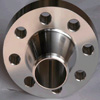 Weld neck flanges are flanges that are designed to be integrated into piping systems by what industry welders describe as butt welds. The production of these flanges is more expensive because of the long necks that are present. Weld neck flanges are preferred for use in high-stress applications. By welding pipe to the neck of the flange stress is transferred to the pipe. The inside diameter of the flange is machined to match the inside diameter of the tube reducing friction and obstruction of flow. The flanges are also available in some different types of material such as copper, stainless, cast iron, galvanized steel, as well as aluminum. There some advantages when we use this kind of flange along with just a few disadvantages.
Key Features:
- Most commonly stocked flange due to the fact that one size fits all pipe schedules.
- Fabricators can more easily cut pipe to length for slip-on flanges and their smaller thickness allows for easier alignment of bolting holes
- ASME B16.5 code limits their usage for 1500#-2500# (lbs.) applications and they are generally not preferred for high pressure temperature environments.
4″ Class 150 Weld Neck Raised Face Flange
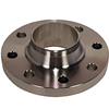
- Bolt Diameter:5/8"
- Bolt Hole Diameter:7-1/2"
- Class:150
- Flange Outer Diameter:9.00"
- Hub Diameter:5.31"
- Length Through Hub:1.31"
- Material:Steel
- Number of Holes:8
- Pipe Size:4"
- Specification:ASTM A 105, ANSI B16.5
- Style:Raised Face
- Thickness:0.94"
- Type:Weld Neck Flange
- Product Weight: 13 lbs
6″ Class 150 Weld Neck Raised Face Steel Flange
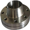
- Bolt Diameter:3/4"
- Bolt Hole Diameter:9-1/2"
- Class:150
- Flange Outer Diameter:11.00"
- Hub Diameter:7.56"
- Length Through Hub:1.56"
- Material:Steel
- Number of Holes:8
- Pipe Size:6"
- Specification:ASTM A 105, ANSI B16.5
- Style:Raised Face
- Thickness:1.00"
- Type:Weld Neck Flange
- Product Weight: 19 lbs
Weld Neck Flange price list
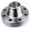
carbon steel a105 ansi Welding Neck/Socket welding flange specifications on stock for sale
US $1-2.5 / Kilogram
ansi b16.5 rasied face weld neck flange
US $0.9-38.4 / Piece
DIN standard slip blind forged ansi welding neck forging pipe stainless steel flange
US $1-500 / Piece
Best Price Titanium Flange to ANSI B16.5 Welding Neck
US $15-100 / Piece
Types of Weld Neck Flange, WNRF flanges Types
| SS 310 / 310S Weld Neck Flanges | • | Duplex Steel UNS S31803 Weld Neck Flanges | |
| • | Stainless Steel 304 / 304L Weld Neck Flanges | • | Duplex Steel Weld Neck Flanges |
| • | Stainless Steel 316 / 316L Weld Neck Flanges | • | Duplex Steel UNS S32205 Weld Neck Flanges |
| • | Stailess Steel 321 / 321H Weld Neck Flanges | • | Super Duplex UNS S32750 Weld Neck Flanges |
| • | Monel 400 Weld Neck Flanges | • | Hastelloy C276 Weld Neck Flanges |
| • | SS Weld Neck Flanges | • | Steel Weld Neck Flanges |
| • | Inconel 625 Weld Neck Flanges | • | Alloy 20 Weld Neck Flanges |
| • | Cu-Ni 70/30 (C71500) Weld Neck Flanges | • | Cu-Ni 90/10 (C70600) Weld Neck Flanges |
| • | ASTM A105 Weld Neck Flanges | • | ASTM A350 LF2 / LF3 Weld Neck Flanges |
| • | Inconel 600 Weld Neck Flanges | • | Hastelloy B2 Weld Neck Flanges |
| • | SS 317 / 317L Weld Neck Flanges | • | Super Duplex Weld Neck Flanges |
| • | SS 347 Weld Neck Flanges | • | Super Duplex UNS S32950 Weld Neck Flanges |
| • | Monel K500 Weld Neck Flanges | • | Hastelloy C22 Weld Neck Flanges |
| • | Stainless Steel 446 Weld Neck Flanges | • | ANSI Weld Neck Flanges |
| • | Inconel 718 Weld Neck Flanges | • | 904L Weld Neck Flanges |
| • | Incoloy 800 Weld Neck Flanges | • | Titanium Gr 2 Weld Neck Flanges |
| • | Incoloy 825 Weld Neck Flanges | • | Titanium Gr 5 Weld Neck Flanges |
