SS Flange Specifications
ANSI B16.5 – Steel Pipe Flanges – Maximum Pressure and Temperature Ratings
Maximum allowable non-shock pressure (psig) and temperature ratings for steel pipe flanges and flanged fittings according the American National Standard ANSI B16.5 – 1988.
| Maximum Allowable non-shock Pressure (psig) | |||||||
| Temperature
(oF) |
Pressure Class (lb) | ||||||
| 150 | 300 | 400 | 600 | 900 | 1500 | 2500 | |
| Hydrostatic Test Pressure (psig) | |||||||
| 450 | 1125 | 1500 | 2225 | 3350 | 5575 | 9275 | |
| -20 to 100 | 290 | 750 | 1000 | 1500 | 2250 | 3750 | 6250 |
| 200 | 260 | 750 | 1000 | 1500 | 2250 | 3750 | 6250 |
| 300 | 230 | 730 | 970 | 1455 | 2185 | 3640 | 6070 |
| 400 | 200 | 705 | 940 | 1405 | 2110 | 3520 | 5865 |
| 500 | 170 | 665 | 885 | 1330 | 1995 | 3325 | 5540 |
| 600 | 140 | 605 | 805 | 1210 | 1815 | 3025 | 5040 |
| 650 | 125 | 590 | 785 | 1175 | 1765 | 2940 | 4905 |
| 700 | 110 | 555 | 740 | 1110 | 1665 | 2775 | 4630 |
| 750 | 95 | 505 | 675 | 1015 | 1520 | 2535 | 4230 |
| 800 | 80 | 410 | 550 | 825 | 1235 | 2055 | 3430 |
| 850 | 65 | 320 | 425 | 640 | 955 | 1595 | 2655 |
| 900 | 50 | 225 | 295 | 445 | 670 | 1115 | 1855 |
| 950 | 35 | 135 | 185 | 275 | 410 | 685 | 1145 |
| 1000 | 20 | 85 | 115 | 170 | 255 | 430 | 715 |
stainless steel flange astm specification
ASTM standards define the specific manufacturing process of the material and determine the exact chemical composition of pipes, fittings and flanges, through percentages of the permitted quantities of carbon, magnesium, nickel, etc., and are indicated by “Grade”.
For example, a carbon steel pipe can be identified with Grade A or B, a stainless-steel pipe with Grade TP304 or Grade TP321, a carbon steel fitting with Grade WPB etc..
Below you will find as an example 3 tables with chemical requirements for:
- Flanges according to ASTM A182 Grade F304, F304L F316L
- Pipes according to ASTM A312 Grade TP304, TP304L, TP3016L
- Fittings according to ASTM A403 Grade WP304, WP304L, WP316L
Furthermore, a table with frequently used ASTM Grades, arranged on Pipes, Fittings, Flanges, Valves, Bolts & Nuts, which belong together as a group.
As you may be have noted, in the table below, ASTM A105 has no Grade. Sometimes ASTM A105N is described;
N stands not for Grade, but for normalized. Normalizing is a type of heat treatment, applicable to ferrous metals only. The purpose of normalizing is to remove the internal stresses induced by heat treating, casting, forming etc
| Flanges according to ASTM A182 | ||||||||
| Grade | C | Mn | P | S | Si | Ni | Cr | Mo |
| F304 | 0.08 | 2.0 | 0.045 | 0.030 | 1.0 | 8.0-11.0 | 18.0-20.0 | |
| F304L | 0.030 | 2.0 | 0.045 | 0.030 | 1.0 | 8.0-13.0 | 18.0-20.0 | |
| F316L | 0.030 | 2.0 | 0.045 | 0.030 | 1.0 | 10.0-15.0 | 16.0-18.0 | 2.0-3.0 |
stainless steel flange chart
| Standard | Class | Diameter | Bolt Circle Diameter | Number of Bolts | Bolt Size | Diameter of Bolt Hole |
|---|---|---|---|---|---|---|
| AS4087 | PN14 | 95 | 67 | 4 | M12 | 14 |
| AS 2129 | Table C | 95 | 67 | 4 | 13 | 14 |
| Table D | 95 | 67 | 4 | 13 | 14 | |
| Table E | 95 | 67 | 4 | 13 | 14 | |
| Table F | 95 | 67 | 4 | 13 | 14 | |
| Table H | 114 | 83 | 4 | 16 | 17 | |
| Table J | 114 | 83 | 4 | 16 | 17 | |
| ANSI B16.5 | ANSI 150 | 89 | 60 | 4 | 13 | 16 |
| ANSI 300 | 95 | 67 | 4 | 13 | 16 | |
| ANSI 600 | 95 | 67 | 4 | 13 | 16 | |
| ANSI 900 | 121 | 83 | 4 | 19 | 22 | |
| ANSI 1500 | 121 | 83 | 4 | 19 | 22 | |
| ISO 7005 (DIN) | PN6 | 80 | 55 | 4 | M10 | 11 |
| PN10 | 95 | 65 | 4 | M12 | 14 | |
| PN16 | 95 | 65 | 4 | M12 | 14 | |
| PN20 | 90 | 60.5 | 4 | M14 | 16 | |
| PN25 | 95 | 65 | 4 | M12 | 14 | |
| PN40 | 95 | 65 | 4 | M12 | 14 |
| Standard | Class | Diameter | Bolt Circle Diameter | Number of Bolts | Bolt Size | Diameter of Bolt Hole |
|---|---|---|---|---|---|---|
| AS4087 | PN14 | 100 | 73 | 4 | M12 | 14 |
| AS 2129 | Table C | 100 | 73 | 4 | 13 | 14 |
| Table D | 100 | 73 | 4 | 13 | 14 | |
| Table E | 100 | 73 | 4 | 13 | 14 | |
| Table F | 100 | 73 | 4 | 13 | 14 | |
| Table H | 115 | 83 | 4 | 16 | 18 | |
| Table J | 115 | 83 | 4 | 16 | 18 | |
| ANSI B16.5 | ANSI 150 | 98 | 70 | 4 | 13 | 16 |
| ANSI 300 | 117 | 83 | 4 | 16 | 19 | |
| ANSI 600 | 117 | 83 | 4 | 16 | 19 | |
| ANSI 900 | 130 | 89 | 4 | 19 | 22 | |
| ANSI 1500 | 130 | 89 | 4 | 19 | 22 | |
| ISO 7005 (DIN) | PN6 | 90 | 65 | 4 | M10 | 11 |
| PN10 | 105 | 75 | 4 | M12 | 14 | |
| PN16 | 105 | 75 | 4 | M12 | 14 | |
| PN20 | 100 | 70 | 4 | M14 | 16 | |
| PN25 | 105 | 75 | 4 | M12 | 14 | |
| PN40 | 105 | 75 | 4 | M12 | 14 |
ss 316 flange pressure rating
Stainless Steel Flanges – ASME/ANSI Class 300
ASME/ANSI B16.5-1996 Pipe Flanges and Flanged Fittings – Class 300 Flanges – outside and inside diameters, bolt circles, numbers and diameters of bolts
Carbon and stainless steel qualities according ASME B16.5 Table 1A.
| Pipe Size
(inches) |
Flange Outside Diameter
(inches) |
Pipe Outside Diameter
(inches) |
Number of Bolt Holes | Bolt Hole Diameter
(inches)1) |
Bolt Circle
(inches) |
| 1/2 | 3-3/4 | 0.84 | 4 | 5/8 | 2-5/8 |
| 3/4 | 4-5/8 | 1.05 | 4 | 3/4 | 3-1/4 |
| 1 | 4-7/8 | 1.32 | 4 | 3/4 | 3-1/2 |
| 1-1/4 | 5-1/4 | 1.66 | 4 | 3/4 | 3-7/8 |
| 1-1/2 | 6-1/8 | 1.90 | 4 | 7/8 | 4-1/2 |
| 2 | 6-1/2 | 2.38 | 8 | 3/4 | 5 |
| 2-1/2 | 7-1/2 | 2.88 | 8 | 7/8 | 5-7/8 |
| 3 | 8-1/4 | 3.50 | 8 | 7/8 | 6-5/8 |
| 3-1/2 | 9 | 4.00 | 8 | 7/8 | 7-1/4 |
| 4 | 10 | 4.50 | 8 | 7/8 | 7-7/8 |
| 5 | 11 | 5.56 | 8 | 7/8 | 9-1/4 |
| 6 | 12-1/2 | 6.63 | 12 | 7/8 | 10-5/8 |
| 8 | 15 | 8.63 | 12 | 1 | 13 |
| 10 | 17-1/2 | 10.75 | 16 | 1-1/8 | 15-1/4 |
| 12 | 20-1/2 | 12.75 | 16 | 1-1/4 | 17-3/4 |
| 14 | 23 | 14.00 | 20 | 1-1/4 | 20-1/4 |
| 16 | 25-1/2 | 16.00 | 20 | 1-3/8 | 22-1/2 |
| 18 | 28 | 18.00 | 24 | 1-3/8 | 24-3/4 |
| 20 | 30-1/2 | 20.00 | 24 | 1-3/8 | 27 |
| 24 | 36 | 24.00 | 24 | 1-5/8 | 32 |
1) Recommended bolts are 1/8 smaller than the nominal bolt hole diameters shown.
stainless steel flange hs code
| Hs Code | Description | Destination | Port of Loading | Unit | Quantity | Value (INR) | Per Unit (INR) |
|---|---|---|---|---|---|---|---|
| 73072100 | ALLOY STEEL INCLUDING STAINLESS STEEL FORGED FLANGES 316L 03300-1811-0661 FLANGE ANSI B16.5 MACHINED 6 INCH 600# 316L SS | United States | Bombay Air Cargo | PCS | 1 | 26,919 | 26,919 |
| 73072100 | ALLOY STEEL INCLUDING STAINLESS STEEL FORGED FLANGES 316L 02100-1811-0301 FLANGE 3 INCH CL150,ASME B16.5, SS | United States | Bombay Air Cargo | PCS | 12 | 36,777 | 3,065 |
| 73072100 | ALLOY STEEL INCLUDING STAINLESS STEEL FORGED FLANGES 316L 02100-1811-0401 FLANGE 4 INCH CL 150, ASME B16.5, SS | Singapore | Bombay Air Cargo | PCS | 3 | 5,986 | 1,995 |
| 73072100 | ALLOY STEEL INCLUDING STAINLESS STEEL FORGED FLANGES 316L 02100-1811-0101 FLANGE 1 INCH CL 150 ASME B16.5, SS | Singapore | Bombay Air Cargo | PCS | 1 | 306 | 306 |
| 73071900 | TUBE OR PIPES FITTINGS. FLANGE, PIPE;STUB END,2IN,SS ASTM 403S,TP316L,40S,BW, BE,LENGTH: MSS-A[SHORT]. | Saudi Arabia | Nhava Sheva Sea | PCS | 60 | 16,384 | 273 |
| 73072100 | ALLOY STEEL INCLUDING STAINLESS STEEL FORGED FLANGES 316L 02100-1811-0401 FLANGE 4 INCH CL150, ASME B16.5, SS | United States | Bombay Air Cargo | PCS | 11 | 44,365 | 4,033 |
| 73072200 | FLANGES ASME B16.5 RF ASTM A182 GR F316/316L 3/4 FLANGE SW CL150 ASME B16.5 SS316 | Lebanon | Bombay Air Cargo | PCS | 112 | 35,109 | 313 |
| 73072200 | FLANGES ASME B16.5 RF ASTM A182 GR F316/316L 1 BLIND FLANGE RF #150 ASME B16.5SS316 | Lebanon | Bombay Air Cargo | PCS | 2 | 823 | 411 |
| 73072200 | FLANGES ASME B16.5 RF ASTM A182 GR F316/316L 1.25 FLANGE SW #150 SS316 | Lebanon | Bombay Air Cargo | PCS | 5 | 2,282 | 456 |
table e stainless steel flange dimensions
Table E Dimensions (In mm)
|
N.B Size |
||||||||||||||
|
D |
K |
L |
A |
C |
N1 |
N2 |
B |
H1 |
H2 |
R1 |
R2 |
No.Holes |
||
|
Ins |
Mm |
|||||||||||||
|
½” |
15 |
95.3 |
66.8 |
14.5 |
21.3 |
6.4 |
27.0 |
33.3 |
22.4 |
9.5 |
22.2 |
6.4 |
1.6 |
4 |
|
¾” |
20 |
101.6 |
73.2 |
14.5 |
26.7 |
6.4 |
33.3 |
38.1 |
27.7 |
11.1 |
22.2 |
6.4 |
1.6 |
4 |
|
1″ |
25 |
114.3 |
82.6 |
14.5 |
33.5 |
7.2 |
42.9 |
47.6 |
34.6 |
11.1 |
22.2 |
6.4 |
1.6 |
4 |
|
1 ¼” |
32 |
120.7 |
87.4 |
14.5 |
42.2 |
7.9 |
49.2 |
55.6 |
43.2 |
11.1 |
25.4 |
6.4 |
1.6 |
4 |
|
1 ½” |
40 |
133.4 |
98.6 |
14.5 |
48.3 |
8.7 |
58.7 |
61.9 |
49.5 |
12.7 |
28.6 |
6.4 |
1.6 |
4 |
|
2″ |
50 |
152.4 |
114.3 |
17.5 |
60.5 |
9.5 |
69.9 |
74.6 |
62.0 |
12.7 |
28.6 |
6.4 |
1.6 |
4 |
|
2 ½” |
65 |
165.1 |
127.0 |
17.5 |
73.2 |
10.3 |
82.6 |
90.5 |
74.7 |
15.9 |
31.8 |
6.4 |
1.6 |
4 |
|
3″ |
80 |
184.2 |
146.1 |
17.5 |
88.9 |
11.1 |
101.6 |
106.4 |
90.7 |
15.9 |
34.9 |
6.4 |
1.6 |
4 |
|
3 ½” |
88 |
203.2 |
165.1 |
17.5 |
101.6 |
11.9 |
114.3 |
119.1 |
103.4 |
17.5 |
34.9 |
6.4 |
1.6 |
4 |
|
4″ |
100 |
215.9 |
177.8 |
17.5 |
114.3 |
12.7 |
130.2 |
133.4 |
116.1 |
19.1 |
41.3 |
9.5 |
3.2 |
4 |
|
5″ |
125 |
254.0 |
209.6 |
17.5 |
141.2 |
14.3 |
152.4 |
160.3 |
143.8 |
19.1 |
44.5 |
9.5 |
3.2 |
8 |
|
6″ |
150 |
279.4 |
235.0 |
17.5 |
168.4 |
17.5 |
184.2 |
185.7 |
171.7 |
19.1 |
47.6 |
9.5 |
3.2 |
8 |
|
8″ |
200 |
336.6 |
292.1 |
17.5 |
219.2 |
19.1 |
241.3 |
241.3 |
221.5 |
22.2 |
50.8 |
9.5 |
3.2 |
8 |
|
10″ |
250 |
406.4 |
355.6 |
22.2 |
273.1 |
22.2 |
292.1 |
298.5 |
276.4 |
27.0 |
63.5 |
9.5 |
3.2 |
8 |
|
12″ |
300 |
457.2 |
406.4 |
22.2 |
323.9 |
25.4 |
342.9 |
349.3 |
325.9 |
28.6 |
69.9 |
9.5 |
4.8 |
12 |
|
14″ |
350 |
527.1 |
469.9 |
25.4 |
355.6 |
28.6 |
406.4 |
– |
359.2 |
– |
73.0 |
9.5 |
4.8 |
12 |
|
16″ |
400 |
577.9 |
520.7 |
25.4 |
406.4 |
31.8 |
431.8 |
– |
410.5 |
– |
– |
– |
– |
12 |
|
18″ |
450 |
641.4 |
584.2 |
25.4 |
457.2 |
34.9 |
– |
– |
461.8 |
– |
– |
– |
– |
12 |
|
20″ |
500 |
704.9 |
641.4 |
25.4 |
508.0 |
38.1 |
– |
– |
513.1 |
– |
– |
– |
– |
16 |
|
24″ |
600 |
825.5 |
755.7 |
28.7 |
609.6 |
47.6 |
– |
– |
616.0 |
– |
– |
– |
– |
16 |
table d stainless steel flange dimensions
Table D Dimensions (In mm)
|
N.B Size |
||||||||||||||
|
D |
K |
L |
A |
C |
N1 |
N2 |
B |
H1 |
H2 |
R1 |
R2 |
No. Holes |
||
|
Ins |
Mm |
|||||||||||||
|
½” |
15 |
95.3 |
66.8 |
14.5 |
21.3 |
4.8 |
27.0 |
33.3 |
22.4 |
9.5 |
22.2 |
6.4 |
1.6 |
4 |
|
¾” |
20 |
101.6 |
73.2 |
14.5 |
26.7 |
4.8 |
33.3 |
38.1 |
27.7 |
11.1 |
22.2 |
6.4 |
1.6 |
4 |
|
1″ |
25 |
114.3 |
82.6 |
14.5 |
33.5 |
4.8 |
42.9 |
47.6 |
34.6 |
11.1 |
22.2 |
6.4 |
1.6 |
4 |
|
1 ¼” |
32 |
120.7 |
87.4 |
14.5 |
42.2 |
6.4 |
49.2 |
55.6 |
43.2 |
11.1 |
25.4 |
6.4 |
1.6 |
4 |
|
1 ½” |
40 |
133.4 |
98.6 |
14.5 |
48.3 |
6.4 |
58.7 |
61.9 |
49.5 |
12.7 |
28.6 |
6.4 |
1.6 |
4 |
|
2″ |
50 |
152.4 |
114.3 |
17.5 |
60.5 |
7.9 |
69.9 |
74.6 |
62.0 |
12.7 |
28.6 |
6.4 |
1.6 |
4 |
|
2 ½” |
65 |
165.1 |
127.0 |
17.5 |
73.2 |
7.9 |
82.6 |
90.5 |
74.7 |
15.9 |
31.8 |
6.4 |
1.6 |
4 |
|
3″ |
80 |
184.2 |
146.1 |
17.5 |
88.9 |
9.7 |
101.6 |
106.4 |
90.7 |
15.9 |
34.9 |
6.4 |
1.6 |
4 |
|
3 ½” |
88 |
203.2 |
165.1 |
17.5 |
101.6 |
9.7 |
114.3 |
119.1 |
103.4 |
17.5 |
34.9 |
6.4 |
1.6 |
4 |
|
4″ |
100 |
215.9 |
177.8 |
17.5 |
114.3 |
9.7 |
130.2 |
133.4 |
116.1 |
19.1 |
41.3 |
9.5 |
3.2 |
4 |
|
5″ |
125 |
254.0 |
209.6 |
17.5 |
141.2 |
12.7 |
152.4 |
160.3 |
143.8 |
19.1 |
44.5 |
9.5 |
3.2 |
8 |
|
6″ |
150 |
279.4 |
235.0 |
17.5 |
168.4 |
12.7 |
184.2 |
185.7 |
171.7 |
19.1 |
47.6 |
9.5 |
3.2 |
8 |
|
8″ |
200 |
336.6 |
292.1 |
17.5 |
219.2 |
12.7 |
241.3 |
241.3 |
221.5 |
22.2 |
50.8 |
9.5 |
3.2 |
8 |
|
10″ |
250 |
406.4 |
355.6 |
22.2 |
273.1 |
16.0 |
292.1 |
298.5 |
276.4 |
27.0 |
63.5 |
9.5 |
3.2 |
8 |
|
12″ |
300 |
457.2 |
406.4 |
22.2 |
323.9 |
19.1 |
342.9 |
349.3 |
325.9 |
28.6 |
69.9 |
9.5 |
4.8 |
12 |
|
14″ |
350 |
527.1 |
469.9 |
25.4 |
355.6 |
22.2 |
406.4 |
– |
359.2 |
– |
73.0 |
9.5 |
4.8 |
12 |
|
16″ |
400 |
577.9 |
520.7 |
25.4 |
406.4 |
22.2 |
– |
– |
410.5 |
– |
– |
– |
– |
12 |
|
18″ |
450 |
641.4 |
584.2 |
25.4 |
457.2 |
25.4 |
– |
– |
461.8 |
– |
– |
– |
– |
12 |
|
20″ |
500 |
704.9 |
641.4 |
25.4 |
508.0 |
28.6 |
– |
– |
513.1 |
– |
– |
– |
– |
16 |
|
24″ |
600 |
825.5 |
755.7 |
28.7 |
609.6 |
31.8 |
– |
– |
616.0 |
– |
– |
– |
– |
16 |
stainless steel spectacle blind flanges
It is also called as Figure-8 Blind.
It is generally a piece of metal that is cut to fit between two pipe flanges and usually sandwiched between two gaskets. a spectacle blind is often made from two metal discs that are attached to each other by a small section of steel. The shape is similar to a pair of glasses or “spectacles” – hence the name spectacle blind. One end of the blind will have an opening to allow flow through the pipe during operation and the other end is solid to block flow during maintenance. They are generally installed as a permanent device to separate process piping systems.
The whole idea of a spectacle blind is so that one can be absolutely sure that an item of equipment is properly and securely blanked off with no possibility of any flow or leakage through a valve during maintenance. The flow can be diverted to other items of equipment but not just bypassed around the blank as this would compromise the safety function of the spectacle blind. The flow has to valved off and pressure relieved prior to loosening flange bolts and swinging the blind.
These Flanges are available in the following range.
Duplex Stainless Steel: UNS S31803, UNS S32750
Carbon Steel: ASTM a105,
Alloy Steel: ASTM a182 F1, F11, F22, F5, F9, F91
Nickel Alloys: Monel 400 & 500, Inconel 600 & 625, Incoloy 800, 825, Hastelloy C22, C276
Copper Alloys: Copper, Brass & Gunmetal
Size: 1/8″ NB TO 48″NB.
Class: 150#, 300#, 400#, 600#, 900#, 1500#, 2500#Dimensional Standard
ANSI: ANSI B16.5, ANSI B16.47, MSS SP44, ANSI B16.36, ANSI B16.48
DIN: DIN 2527, DIN 2566, DIN 2573, DIN 2576, DIN 2641, DIN 2642, DIN 2655, DIN 2656, DIN 2627, DIN 2628, DIN 2629, DIN 2631, DIN 2632, DIN 2633, DIN 2634, DIN 2635, DIN 2636, DIN 2637, DIN 2638, DIN 2673
B.S: BS 4504, BS4504, BS1560, BS10
stainless steel reducing flange dimensions
Specifications :
| Size | : | ½” (15 NB) to 48″ (1200NB) |
| Class | : | 150#, 300#,400 #,600#,900#, 1500# & 2500 #. |
| Standards | : | ANSI B16.5, ANSI B16.47, MSS SP44, ANSI B16.36, ANSI B16.48 |
| DIN | : | DIN2527, DIN2566, DIN2573, DIN2576, DIN2641, DIN2642, DIN2655, DIN2656, DIN2627, DIN2628, DIN2629, DIN 2631, DIN2632, DIN2633, DIN2634, DIN2635, DIN2636, DIN2637, DIN2638, DIN2673 |
| B.S | : | BS4504 , BS4504, BS1560, BS10 |
Grades :
Stainless Steel Reducing Flanges :
ASTM A 182, A 240, F 304, 304L, 304H, 316, 316L, 316Ti, 310, 310S, 321, 321H, 317, 347, 347H, 904L.
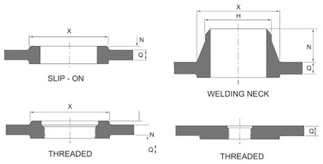
ASME B16.5 Reducing Flanges Dimension
stainless steel orifice flange manufacturers
Orifice Flanges are used with orifice meters for the purpose of measuring the flow rate of either liquids or gases in the respective pipeline. Orifice flanges generally come with either raised faces or RTJ (Ring Type Joint) facings. They are, for all intensive purposes, the same as weld neck and slip-on flanges with extra machining. They have modifications of radial tapped holes in the flange ring for meter connections and orifice plate carriers for the reason of fitting meter connections. The additional bolts act as a jack to allow the separation of the two flanges to change the orifice plate or for other inspection services. We offers these flanges in stainless steel material.
| Specification | ASTM B366, ASTM SB 366, ASTM B564, ASME SB564 |
| Grade | ASTM A182 F202, F304/304L/304H, F316/316L, F316H, F316TI, F310, F321, F904L |
| Standard | ANSI Flanges, ASME Flanges, BS Flanges, DIN Flanges, EN Flanges, etc. |
| Size | 1/8″ to 36″/ |
| Dimensions | ANSI/ASME B16.5, B 16.47 Series A & B, B16.48, BS4504, BS 10, EN-1092, DIN, etc. |
| Class / Pressure | 150#, 300#, 600#, 900#, 1500#, 2500#, PN6, PN10, PN16, PN25, PN40, PN64 etc. |
stainless steel loose flange
Stainless steel loose flanges – type 02, PN 10, EN 1092-1
Available in grades: 1.4301 (304), 1.4307 (304L), 1.4541 (321), 1.4571 (316Ti), 1.4404 (316L).
Dw* – for tubes with ISO diameters
| DN | Outside diameter | Bore diameter | Thickness | Diameter for bolt circle | Bolting |
Diameter for bolt hole |
Weight
kg |
|
| Dz | Dw* | g | Dp | Number | Size | Do | ||
| 10 | 90 | 21 | 14 | 60 | 4 | M12 | 14 | 0.591 |
| 15 | 95 | 25 | 14 | 65 | 4 | M12 | 14 | 0.654 |
| 20 | 105 | 31 | 16 | 75 | 4 | M12 | 14 | 0.909 |
| 25 | 115 | 38 | 16 | 85 | 4 | M12 | 14 | 1.08 |
| 32 | 140 | 47 | 18 | 100 | 4 | M16 | 18 | 1.77 |
| 40 | 150 | 53 | 18 | 110 | 4 | M16 | 18 | 2.02 |
| 50 | 165 | 61 | 20 | 125 | 4 | M16 | 18 | 2.52 |
| 65 | 185 | 81 | 20 | 145 | 8 | M16 | 18 | 3.05 |
| 80 | 200 | 94 | 20 | 160 | 8 | M16 | 18 | 3.48 |
| 100 | 220 | 120 | 22 | 180 | 8 | M16 | 18 | 4.2 |
| 125 | 250 | 145 | 22 | 210 | 8 | M16 | 18 | 5.21 |
| 150 | 285 | 174 | 24 | 240 | 8 | M20 | 22 | 6.89 |
| 200 | 340 | 226 | 24 | 295 | 8 | M20 | 22 | 8.87 |
| 250 | 395 | 281 | 26 | 350 | 12 | M20 | 22 | 11.2 |
| 300 | 445 | 333 | 26 | 400 | 12 | M20 | 22 | 12.8 |
| 350 | 505 | 365 | 30 | 460 | 16 | M20 | 22 | 19.4 |
| 400 | 565 | 416 | 32 | 515 | 16 | M24 | 26 | 26.4 |
| 450 | 615 | 467 | 36 | 565 | 20 | M24 | 26 | 32.2 |
| 500 | 670 | 519 | 38 | 620 | 20 | M24 | 26 | 38.5 |
| 600 | 780 | 622 | 42 | 725 | 20 | M27 | 30 | 52.2 |
| 700 | 895 | 721 | 50 | 840 | 24 | M27 | 30 | 79.4 |
| 800 | 1015 | 824 | 56 | 950 | 24 | M30 | 33 | 112.0 |
| 900 | 1115 | 926 | 62 | 1050 | 28 | M30 | 33 | 135.0 |
| 1000 | 1230 | 1028 | 70 | 1160 | 28 | M33 | 36 | 180.0 |
stainless steel flange weight chart
ANSI B16.5 -½ “-24” Forged Flanges
| CLASS | Nominal Pipe Size | Slip On | Threaded | Socket Weld | Lap Joint | Blind | Weld Neck |
| 150 lb | ½ | 1 | 1 | 2 | 1 | 2 | 2 |
| ¾ | 2 | 2 | 2 | 2 | 2 | 2 | |
| 1 | 2 | 2 | 2 | 2 | 2 | 3 | |
| 1¼ | 3 | 3 | 3 | 3 | 3 | 3 | |
| 1½ | 3 | 3 | 3 | 3 | 4 | 4 | |
| 2 | 5 | 5 | 5 | 5 | 5 | 6 | |
| 2½ | 8 | 8 | 8 | 8 | 7 | 10 | |
| 3 | 9 | 9 | 9 | 9 | 9 | 11.5 | |
| 3½ | 11 | 12 | 11 | 11 | 13 | 12 | |
| 4 | 13 | 13 | 13 | 13 | 17 | 16.5 | |
| 5 | 15 | 15 | 15 | 15 | 20 | 21 | |
| 6 | 19 | 19 | 19 | 19 | 27 | 26 | |
| 8 | 30 | 30 | 30 | 30 | 47 | 42 | |
| 10 | 43 | 43 | 43 | 43 | 70 | 54 | |
| 12 | 64 | 64 | 64 | 64 | 123 | 88 | |
| 14 | 90 | 90 | 90 | 105 | 140 | 114 | |
| 16 | 106 | 98 | 98 | 140 | 180 | 140 | |
| 18 | 130 | 130 | 130 | 160 | 220 | 165 | |
| 20 | 165 | 165 | 165 | 195 | 285 | 197 | |
| 22 | 185 | 185 | 185 | 245 | 355 | 225 | |
| 24 | 220 | 220 | 220 | 275 | 430 | 268 | |
| CLASS | Nominal Pipe Size | Slip On | Threaded | Socket Weld | Lap Joint | Blind | Weld Neck |
| 300 lb | ½ | 2 | 2 | 3 | 2 | 2 | 2 |
| ¾ | 3 | 3 | 3 | 3 | 3 | 3 | |
| 1 | 3 | 3 | 3 | 3 | 4 | 4 | |
| 1¼ | 4.5 | 4.5 | 4 | 4.5 | 6 | 5 | |
| 1½ | 6.5 | 6.5 | 6 | 6.5 | 7 | 7 | |
| 2 | 7 | 7 | 7 | 7 | 8 | 9 | |
| 2½ | 10 | 10 | 10 | 10 | 12 | 12 | |
| 3 | 13 | 14 | 13 | 14.5 | 16 | 18 | |
| 3½ | 17 | 17 | 17 | 17 | 21 | 20 | |
| 4 | 23.5 | 24 | 22 | 24 | 28 | 26.5 | |
| 5 | 29 | 31 | 28 | 28 | 37 | 36 | |
| 6 | 39 | 39 | 39 | 39 | 50 | 45 | |
| 8 | 58 | 58 | 58 | 58 | 81 | 69 | |
| 10 | 81 | 81 | 81 | 91 | 124 | 100 | |
| 12 | 115 | 115 | 115 | 140 | 185 | 142 | |
| 14 | 165 | 165 | 165 | 190 | 250 | 206 | |
| 16 | 210 | 220 | 190 | 234 | 315 | 250 | |
| 18 | 253 | 280 | 250 | 305 | 414 | 320 | |
| 20 | 315 | 325 | 315 | 375 | 515 | 400 | |
| 22 | 370 | 370 | 370 | 435 | 640 | 465 | |
| 24 | 490 | 490 | 475 | 550 | 800 | 580 | |
| CLASS | Nominal Pipe Size | Slip On | Threaded | Socket Weld | Lap Joint | Blind | Weld Neck |
| 400 lb | ½ | 2 | 2 | 2 | 2 | 2 | 3 |
| ¾ | 3 | 3 | 3 | 3 | 3 | 3.5 | |
| 1 | 3.5 | 3.5 | 3.5 | 3.5 | 4 | 4 | |
| 1¼ | 4.5 | 4.5 | 4.5 | 4.5 | 6 | 4.5 | |
| 1½ | 6.5 | 6.5 | 6.5 | 6.5 | 8 | 8 | |
| 2 | 8 | 8 | 8 | 8 | 10 | 10 | |
| 2½ | 12 | 12 | 12 | 11 | 15 | 14 | |
| 3 | 15 | 15 | 15 | 14 | 20 | 18 | |
| 3½ | 21 | 21 | 21 | 20 | 29 | 26 | |
| 4 | 26 | 26 | 26 | 25 | 33 | 35 | |
| 5 | 31 | 31 | 31 | 29 | 44 | 43 | |
| 6 | 44 | 44 | 44 | 42 | 61 | 57 | |
| 8 | 67 | 67 | 67 | 64 | 100 | 89 | |
| 10 | 91 | 91 | 91 | 110 | 155 | 125 | |
| 12 | 130 | 130 | 130 | 152 | 226 | 175 | |
| 14 | 191 | 191 | 191 | 210 | 310 | 233 | |
| 16 | 253 | 253 | 253 | 280 | 398 | 295 | |
| 18 | 310 | 310 | 310 | 345 | 502 | 360 | |
| 20 | 378 | 378 | 378 | 420 | 621 | 445 | |
| 22 | 405 | 405 | 405 | 455 | 720 | 505 | |
| 24 | 539 | 539 | 539 | 615 | 936 | 640 | |
| CLASS | Nominal Pipe Size | Slip On | Threaded | Socket Weld | Lap Joint | Blind | Weld Neck |
| 600 lb | ½ | 2 | 2 | 2 | 2 | 3 | 3 |
| ¾ | 3 | 3 | 3 | 3 | 4 | 4 | |
| 1 | 4 | 4 | 4 | 4 | 4 | 4 | |
| 1¼ | 5 | 5 | 5 | 5 | 6 | 6 | |
| 1½ | 7 | 7 | 7 | 7 | 8 | 8 | |
| 2 | 9 | 9 | 9 | 9 | 10 | 12 | |
| 2½ | 13 | 13 | 13 | 12 | 15 | 18 | |
| 3 | 16 | 16 | 16 | 15 | 20 | 23 | |
| 3½ | 21 | 21 | 21 | 20 | 29 | 26 | |
| 4 | 37 | 37 | 37 | 36 | 41 | 42 | |
| 5 | 63 | 63 | 63 | 63 | 68 | 68 | |
| 6 | 80 | 80 | 80 | 78 | 86 | 81 | |
| 8 | 115 | 15 | 15 | 112 | 140 | 120 | |
| 10 | 177 | 177 | 177 | 195 | 231 | 190 | |
| 12 | 215 | 215 | 215 | 240 | 295 | 226 | |
| 14 | 259 | 259 | 259 | 290 | 378 | 347 | |
| 16 | 366 | 366 | 366 | 400 | 527 | 481 | |
| 18 | 476 | 476 | 476 | 469 | 665 | 555 | |
| 20 | 612 | 612 | 612 | 604 | 855 | 690 | |
| 22 | 590 | 590 | 590 | 670 | 1000 | 720 | |
| 24 | 876 | 876 | 876 | 866 | 1250 | 977 | |
| CLASS | Nominal Pipe Size | Slip On | Threaded | Socket Weld | Lap Joint | Blind | Weld Neck |
| 900 lb | ½ | 6 | 6 | 6 | 6 | 4 | 7 |
| ¾ | 6 | 6 | 6 | 6 | 6 | 7 | |
| 1 | 7.5 | 7.5 | 7.5 | 7.5 | 9 | 8.5 | |
| 1¼ | 10 | 10 | 10 | 10 | 10 | 10 | |
| 1½ | 14 | 14 | 14 | 14 | 14 | 14 | |
| 2 | 22 | 22 | 22 | 21 | 25 | 24 | |
| 2½ | 31 | 31 | 31 | 25 | 32 | 31 | |
| 3 | 36 | 36 | 36 | 29 | 35 | 36 | |
| 4 | 53 | 53 | 53 | 51 | 54 | 53 | |
| 5 | 83 | 83 | 83 | 81 | 87 | 86 | |
| 6 | 110 | 110 | 110 | 105 | 115 | 110 | |
| 8 | 172 | 172 | 172 | 190 | 200 | 187 | |
| 10 | 245 | 245 | 245 | 277 | 290 | 268 | |
| 12 | 326 | 326 | 326 | 371 | 415 | 372 | |
| 14 | 400 | 400 | 400 | 415 | 520 | 562 | |
| 16 | 459 | 459 | 459 | 488 | 619 | 685 | |
| 18 | 647 | 647 | 647 | 670 | 880 | 924 | |
| 20 | 792 | 792 | 792 | 868 | 1107 | 1164 | |
| 24 | 1480 | 1480 | 1480 | 1659 | 2099 | 2107 | |
| CLASS | Nominal Pipe Size | Slip On | Threaded | Socket Weld | Lap Joint | Blind | Weld Neck |
| 1500 lb | ½ | 6 | 6 | 6 | 6 | 4 | 7 |
| ¾ | 6 | 6 | 6 | 6 | 6 | 7 | |
| 1 | 8 | 8 | 8 | 8 | 9 | 9 | |
| 1¼ | 10 | 10 | 10 | 10 | 10 | 10 | |
| 1½ | 14 | 14 | 14 | 14 | 14 | 14 | |
| 2 | 25 | 25 | 25 | 25 | 25 | 25 | |
| 2½ | 36 | 36 | 36 | 35 | 35 | 36 | |
| 3 | 48 | 48 | 48 | 47 | 48 | 48 | |
| 4 | 73 | 73 | 73 | 75 | 73 | 73 | |
| 5 | 132 | 132 | 132 | 140 | 140 | 132 | |
| 6 | 165 | 165 | 165 | 170 | 160 | 165 | |
| 8 | 260 | 260 | 260 | 286 | 302 | 275 | |
| 10 | 436 | 436 | 436 | 485 | 510 | 455 | |
| 12 | 667 | 667 | 667 | 749 | 775 | 690 | |
| 14 | 940 | 940 | 940 | 890 | 975 | 940 | |
| 16 | 1250 | 1250 | 1250 | 1250 | 1300 | 1250 | |
| 18 | 1625 | 1625 | 1625 | 1475 | 1750 | 1625 | |
| 20 | 2050 | 2050 | 2050 | 1775 | 2225 | 2050 | |
| 24 | 2825 | 2825 | 2825 | 2825 | 3625 | 3325 | |
| CLASS | Nominal Pipe Size | Slip On | Threaded | Socket Weld | Lap Joint | Blind | Weld Neck |
| 2500 lb | ½ | …. | 7 | …. | 7 | 7 | 8 |
| ¾ | …. | 9 | …. | 8 | 10 | 9 | |
| 1 | …. | 12 | …. | 12 | 12 | 13 | |
| 1¼ | …. | 18 | …. | 17 | 18 | 20 | |
| 1½ | …. | 25 | …. | 24 | 25 | 28 | |
| 2 | …. | 38 | …. | 37 | 39 | 42 | |
| 2½ | …. | 55 | …. | 53 | 56 | 52 | |
| 3 | …. | 83 | …. | 80 | 86 | 94 | |
| 4 | …. | 127 | …. | 122 | 133 | 146 | |
| 5 | …. | 210 | …. | 204 | 223 | 244 | |
| 6 | …. | 323 | …. | 314 | 345 | 378 | |
| 8 | …. | 485 | …. | 471 | 533 | 576 | |
| 10 | …. | 925 | …. | 897 | 1025 | 1068 | |
| 12 | …. | 1300 | …. | 1262 | 1464 | 1608 |
stainless steel flanges manufacturing process
 |
 |
 |
 |
 |
| Stainless Steel ring type joint flanges | Stainless Steel raised face flanges | Stainless Steel Flat face flange supplier | stainless steel flange ansi | stainless steel flange asme |
 |
 |
 |
 |
 |
| Stainless Steel collar flanges | Stainless Steel flat face flanges | Stainless Steel spectacle blind flange bolts | Stainless Steel slip on flanges | Stainless Steel threaded flanges |
